
CAIGOY’s GROUP
RADIO RECEIVER CIRCUIT
10-Einstein
RADIO RECEIVER COMPONENTS:
Antenna: It is a piece or length of wire. It captures radio waves. When exposed to radio waves, the wave induces a minimal alternating current in the antenna.
RF amplifier: It is a sensitive amplifier that amplifies the very weak radio frequency (RF) signal from the antenna to be processed by the tuner.
Tuner: It extracts signals of a particular frequency from different frequencies. The antenna captures radio waves of all the frequencies and sends them to the radio frequency (RF) amplifier, which amplifies them all.
RADIO RECEIVER COMPONENTS:
Detector: It is for the audio information to be separated from the carrier wave. A rectifying diode rectifies the alternating current signal in the AM signals. A direct current signal that feeds to an audio amplifier circuit is what remains on the alternating current once passed into a rectifying diode. The detector circuit is a bit more complicated for FM signals.
Audio amplifier: The weak signal that comes from the detector is amplified by this component using a simple transistor amplifier circuit.
BASIC AM RADIO RECEIVER DIAGRAM
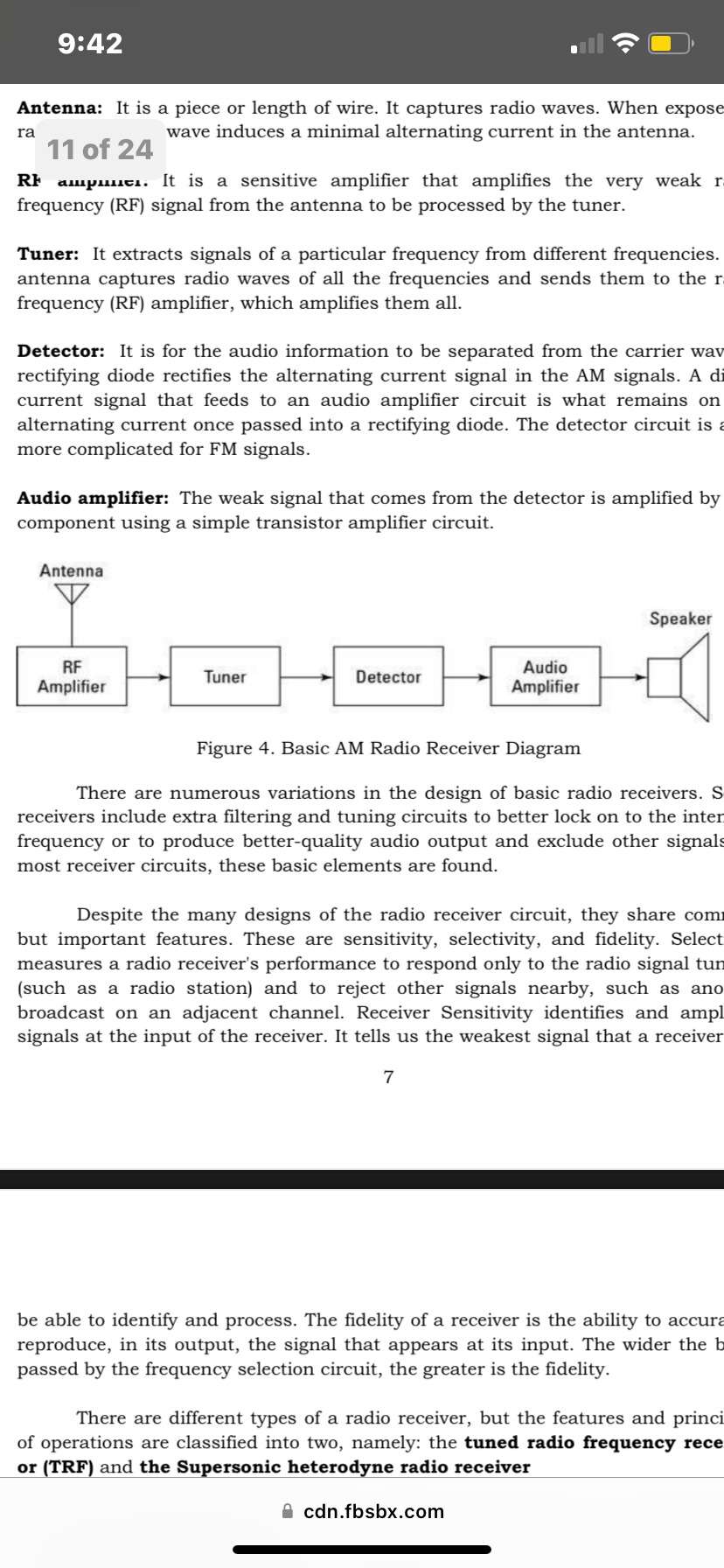
There are numerous variations in the design of basic radio receivers. Some receivers include extra filtering and tuning circuits to better lock on to the intended frequency or to produce better-quality audio output and exclude other signals. In most receiver circuits, these basic elements are found.
Despite the many designs of the radio receiver circuit, they share common but important features. These are sensitivity, selectivity, and fidelity. Selectivity measures a radio receiver's performance to respond only to the radio signal tune in (such as a radio station) and to reject other signals nearby, such as another broadcast on an adjacent channel. Receiver Sensitivity identifies and amplifies signals at the input of the receiver. It tells us the weakest signal that a receiver will be able to identify and process. The fidelity of a receiver is the ability to accurately reproduce, in its output, the signal that appears at its input. The wider the band passed by the frequency selection circuit, the greater is the fidelity.
DIFFERENT TYPES OF RADIO RECEIVER:
There are different types of a radio receiver, but the features and principles of operations are classified into two, namely: the tuned radio frequency receiver or (TRF) and the Supersonic heterodyne radio receiver
Tuned radio frequency (TRF): This was the first radio receiver used. It consists of a tuned circuit and a detector. Tune radio frequency was used in the early years of wireless technology. The Tune Radio Frequency receiver consists of three main sections: Tune radio frequency stages, a signal detector, and an audio amplifier.
Tuned radio frequency stages: These consist of one or more amplifying and tuning stages. Early sets often had several stages, each proving some gain and selectivity.
Signal detector: The detector enables the audio from the amplitude modulation signal to be extracted. It uses a diode to rectify a signal.
Audio amplifier: This is where the audio signal amplifies.
TUNED RADIO FREQUENCY RECEIVER (TRF) BLOCK DIAGRAM
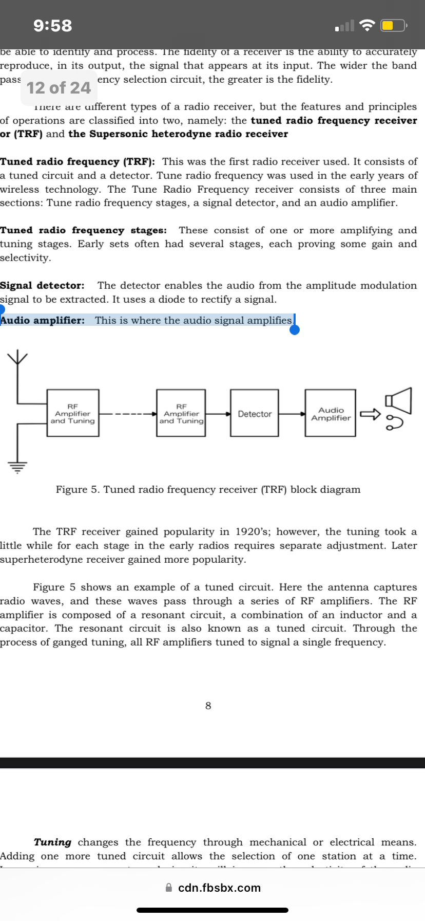
The TRF receiver gained popularity in 1920’s; however, the tuning took a little while for each stage in the early radios requires separate adjustment. Later superheterodyne receiver gained more popularity.
Figure 5 shows an example of a tuned circuit. Here the antenna captures radio waves, and these waves pass through a series of RF amplifiers. The RF amplifier is composed of a resonant circuit, a combination of an inductor and a capacitor. The resonant circuit is also known as a tuned circuit. Through the process of ganged tuning, all RF amplifiers tuned to signal a single frequency.
Tuning changes the frequency through mechanical or electrical means. Adding one more tuned circuit allows the selection of one station at a time. Increasing one or more turned circuits will increase the selectivity of the radio receiver. Tuned amplification includes increased sensitivity and increased selectivity.
The detector reconstructs the information carried by the radio waves. The process of extracting the original information from the carrier wave is called demodulation. A diode, a capacitor, and a resistor make up the detector circuit. It removes high-frequency components. The AM demodulation has two stages. First is the rectification of the amplifier by a diode. Second, the capacitor smooths out the amplitude of the rectified signal. The audio signal is the result of the two stages that will be sent to the audio amplifier to further amplify in the audio frequency amplifier (AF).
The signal is further amplified in an audio frequency (AF) amplifier after detection. The AF amplifier amplifies the weak signal drives, the signal to the loudspeaker or an output device. The signal is increased high enough to drive loads of devices. A speaker is used to hear the audio signal in the form of sound.
TRF receivers are easier to design. It has high sensitivity allowing broadcast frequency from 535 kHz to 1705 kHz. Problems of TRF receivers include difficulty in designing at very high frequency, poor audio quality, instability, and poor selectivity.
DIFFERENT TYPES OF RADIO RECEIVER:
Supersonic heterodyne wireless receiver
It was developed to provide an additional level of selectivity. This uses a heterodyne or mixing process to convert signals done to a fixed intermediate frequency.
Tuning of this radio is through the effective changing of the local oscillator. Broadcast radio receivers, televisions, short wave receivers, and commercial radios have used the superheterodyne principle as the basis of their operation. It was one of the most successful forms of radio being used almost exclusively as the RF circuit design. It was Invented in 1918 and overcoming the selectivity issue making it popular for nearly 100 years.
The superheterodyne was used in every form of radio from domestic broadcast radios to walkie talkies, television sets, through to hi-fi tuners, and professional communications radios, satellite base stations, and much more.
SUPERHETERODYNE RECEIVER SYSTEM DIAGRAM
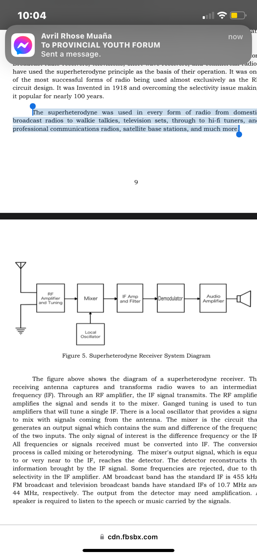
The figure above shows the diagram of a superheterodyne receiver. The receiving antenna captures and transforms radio waves to an intermediate frequency (IF). Through an RF amplifier, the IF signal transmits. The RF amplifier amplifies the signal and sends it to the mixer. Ganged tuning is used to tune amplifiers that will tune a single IF. There is a local oscillator that provides a signal to mix with signals coming from the antenna. The mixer is the circuit that generates an output signal which contains the sum and difference of the frequency of the two inputs. The only signal of interest is the difference frequency or the IF. All frequencies or signals received must be converted into IF. The conversion process is called mixing or heterodyning. The mixer's output signal, which is equal to or very near to the IF, reaches the detector. The detector reconstructs the information brought by the IF signal. Some frequencies are rejected, due to the selectivity in the IF amplifier. AM broadcast band has the standard IF is 455 kHz. FM broadcast and television broadcast bands have standard IFs of 10.7 MHz and 44 MHz, respectively. The output from the detector may need amplification. A speaker is required to listen to the speech or music carried by the signals.
THANK YOU!
—Caigoy’s Group
teacher: Mrs. Edna A. Calimlim